Scan to BIM in one sentence
Scan to BIM is the process of 3D scanning an existing building or piece of infrastructure and turning that measurement into a BIM model. The laser scanner measures millions of points of reality; then a technical team interprets that point cloud and models walls, slabs, columns, pipes or equipment on top of it as BIM objects with their geometry and data.
The sentence is short, but it hides three phases that are best kept apart:
- Capture: going on site and measuring.
- What the scan gives you: a registered point cloud, which is already a useful deliverable in its own right.
- BIM modelling: interpreting the cloud and turning it into a model with objects, types and properties.
Almost everything written about Scan to BIM presents them as one continuous chain. In practice, each has its own cost, its own timeline and its own way of going wrong. And some projects only need the first two.
Phase 1 · Capture: what is measured and with what
Capture is the fieldwork. Its goal is a single one: to record the real geometry of the asset with the accuracy and coverage the model will need. No more, because over-capturing also costs money; and no less, because going back on site costs more.
Terrestrial laser scanner (TLS)
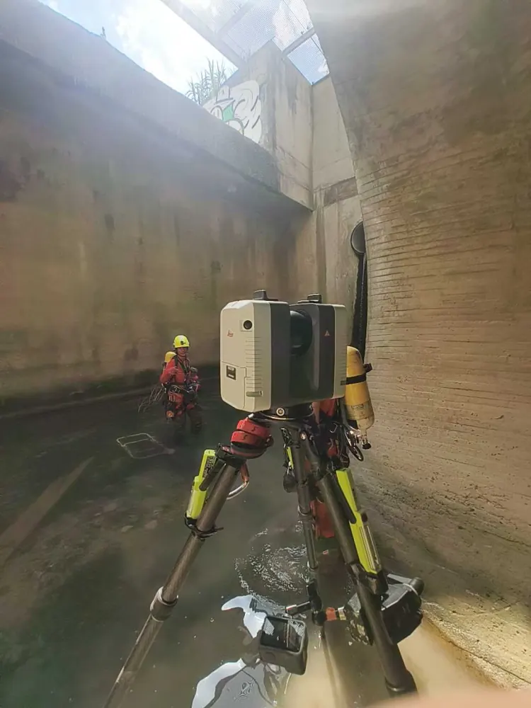
This is the reference tool for Scan to BIM of interiors, building services and structure. The scanner sits on a tripod, rotates on itself and measures distances with a laser beam. A unit such as the Leica RTC360 gives a 3D point accuracy of 1.9 mm at 10 m and 2.9 mm at 20 m according to its datasheet, and captures up to two million points per second. Tens or hundreds of overlapping setups are made until the asset is covered.
SLAM (mobile scanner)
The scanner is handheld or carried in a backpack and measures as you walk. It is much faster over long routes —galleries, warehouses, open-plan floors, heritage buildings with many rooms— in exchange for slightly more noise than the terrestrial scanner. We use it, for example, in heritage surveys where speed and continuity of the route matter more than the last millimetre.
Drone: LiDAR and photogrammetry
For roofs, tall façades, terrain and surroundings, the ground-based scanner cannot reach. A LiDAR drone or one with a photogrammetry camera fills the gap. On a building the normal approach is to combine: terrestrial inside, drone outside, all joined into a single cloud.
Registration and georeferencing
Each scanner setup measures in its own coordinate system. Registration means fitting them all into a single coherent dataset, whether by cloud-to-cloud overlap, targets or control points. Georeferencing means placing that dataset in real-world coordinates (ETRS89 / UTM in Spain) with survey control. If the model has to match mapping, another building or an urban development project, this step is not optional.
Registration is where the accuracy of the whole dataset is won or lost. A millimetre-accurate scanner that is badly registered produces a centimetre-accurate cloud. That is why the registration report —with the mean error between setups— should be part of the delivery.
Phase 2 · What the scan gives you (before modelling anything)
This is the point most often overlooked: once capture and registration are finished, you already have a complete deliverable. It is not BIM yet, but it is enough for many decisions.
| Deliverable | What it is | What it is useful for without modelling |
|---|---|---|
| Registered point cloud | Millions of XYZ points with colour and intensity, in a single coordinate system | Measuring distances, heights and sections; checking whether something fits; the basis for any later modelling |
| 360° panoramas | Spherical photographs taken from each setup | Walking through the asset from the office and seeing labels, conditions and details |
| Orthoimages | Flat, scaled views generated from the cloud | Façade elevations, reflected ceiling plans, inventories of elements |
| 2D sections and plans | Cuts through the cloud at a given level or plane | Drafting existing-condition CAD drawings without going through BIM |
| Web viewer | The cloud published to open in a browser | Sharing with the whole team without software licences |
Point cloud formats
- E57: the neutral format, defined by the ASTM E2807 standard. It stores the points, their attributes and the scanner images. If you only ask for one format, ask for this one.
- RCP / RCS: the Autodesk ReCap format, the one that links directly into Revit and AutoCAD.
- LAS / LAZ: common in surveying, GIS and drone work.
A real example: on the Santillana Canal, for Canal de Isabel II, the main deliverable was the continuous cloud of more than 12 km of conduits. The aim was to document the real condition for inspection and maintenance; there was no need to model every section in BIM for that. You can see it in the full case study.
Phase 3 · BIM modelling: from points to objects
The cloud tells you where something is. The BIM model tells you what it is. Modelling is interpretation: deciding that this set of points is a 30 cm wall, that one is an HEB-200 steel column, that curved surface is a 150 mm pipe with its insulation.
This phase is done by a person, not by the scanner, and it accounts for most of the timeline and the cost. What defines it:
- Software and format. Usually Revit (RVT) with export to IFC, the open format from buildingSMART (ISO 16739-1). There are workflows in Archicad, Tekla or others when the client works with them.
- Disciplines. Architecture, structure, building services (MEP), or only some of them. Each discipline added multiplies the work.
- Level of development (LOD). How much geometry and information each element carries. We explain it in depth in the guide to LOD levels.
- Classification and properties. Which code each object carries (GuBIMClass, Uniclass…) and which data are filled in. Details in BIM classification systems.
- Modelling tolerance. How far the model may deviate from the cloud. It is the next section, and it is the one that prevents the most arguments.
One detail makes all the difference: reality is not straight. Walls lean out of plumb, slabs deflect, pipes are not perfectly parallel. The BIM model, on the other hand, tends towards the ideal. Deciding when the deformation is modelled and when it is “straightened” within tolerance is part of the brief, not a decision the modeller should take on their own.
Scanner accuracy is not model accuracy
This is the most common confusion, and it comes from mixing phases 2 and 3. A scanner that measures with 2 mm accuracy does not mean the BIM model is within 2 mm of reality.
The USIBD LOA (Level of Accuracy) specification separates this neatly into two concepts:
- Measured accuracy: that of the cloud, which comes from capture and registration.
- Represented accuracy: that of the model, in other words how far each modelled object lies from the cloud.
And it defines five levels, expressed at 95% confidence (2σ):
| Level | Range | Typical use |
|---|---|---|
| LOA10 | over 50 mm | Massing, volume studies |
| LOA20 | 15 – 50 mm | Architecture for concept design and refurbishment |
| LOA30 | 5 – 15 mm | Architecture and structure for detailed design, MEP |
| LOA40 | 1 – 5 mm | Industrial elements, fabrication fit-ups |
| LOA50 | 0 – 1 mm | Metrology, very specific cases |
Watch out for a small-print detail: scanner datasheets usually give accuracy at 68% confidence (1σ), whereas LOA refers to 95%. The figures cannot be compared as they stand. In most buildings, LOA20 for architecture and LOA30 for structure and building services is a reasonable starting point.
How to commission a Scan to BIM without surprises
A good brief fits on one page and answers these questions:
- What will the model be used for? Refurbishment, maintenance, tendering, services coordination, inventory. Everything else follows from this.
- Do you need a model, or is the cloud enough? If you are only going to measure and draft floor plans, phase 2 may be sufficient.
- Physical scope: which floors, which areas, interior and exterior, roofs.
- Disciplines and categories: the specific list of what is modelled (walls, doors, columns, downpipes, cable trays…) and what is not.
- LOD and LOA per discipline.
- Coordinate system: local or georeferenced, and in which datum.
- Formats: RVT and version, IFC and version, cloud in E57 and/or RCP.
- Classification and properties that each object must carry.
- Quality control: how the model will be checked against the cloud (ideally, a deviation map).
If you do not have all the answers, that is normal. It is exactly what we define in the first meeting, before sending anyone on site, as we explain in our scanning process.
Mistakes we keep seeing
- Asking for “LOD 400 for everything”. It makes the project more expensive and longer without anyone using that detail. LOD is decided per discipline and per use.
- Not asking for the cloud. The model is an interpretation; the cloud is the measurement. When a question comes up two years from now, the cloud is what answers it. Keep it.
- Scanning without knowing what will be modelled. Areas nobody models get captured and the ones that were needed are missing: suspended ceilings left closed, plant rooms locked, roofs without a drone.
- Not setting the tolerance. Without an agreed LOA, any deviation is debatable and the review becomes one opinion against another.
- Relying on old drawings “to go faster”. The whole point of an as-built is precisely not to depend on them.
If you are preparing a project and want to sanity-check the scope, tell us about it in the form below. We will tell you which phases you really need and which ones you can skip.